Quick Start
Product Overview
The NE100 series is a high-performance smart camera product line designed for IoT applications, with the NE101 standard firmware providing core functions such as timed capture and data reporting. This guide will help you quickly master the usage of the product.
Hardware Preparation
Hardware Components
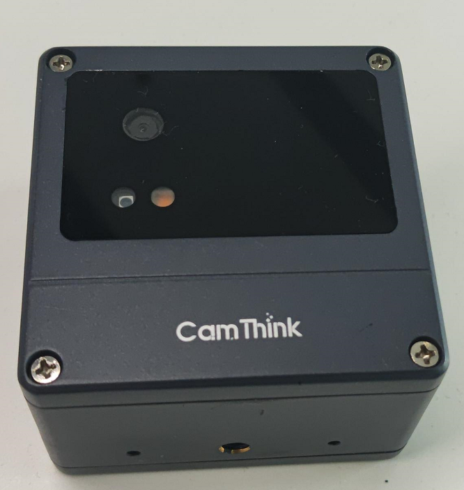
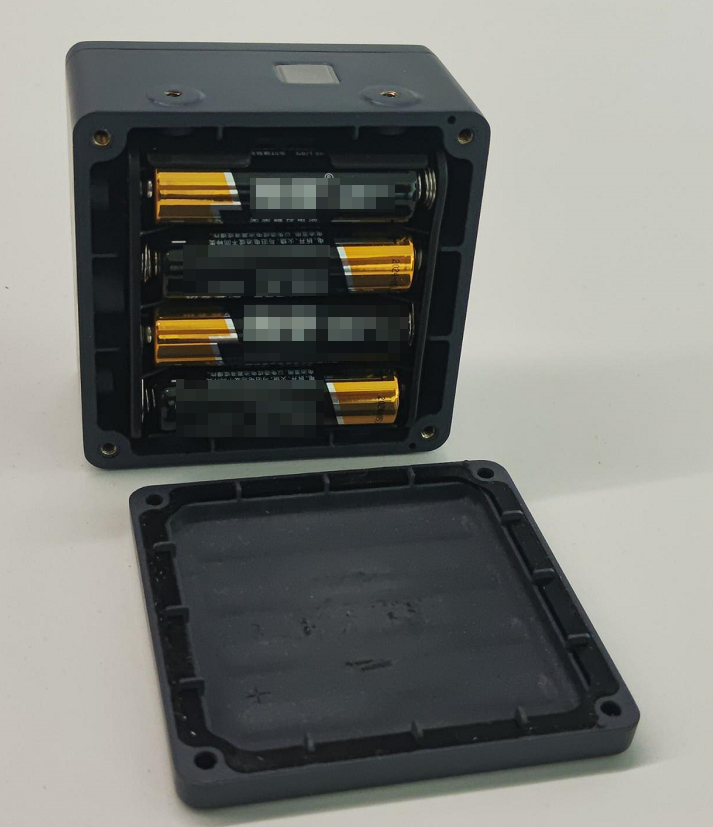
- Complete Device: Includes full enclosure and battery compartment
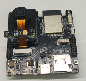
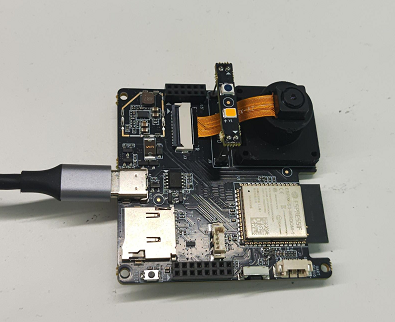
- Development Board: Exposed PCB board for easy debugging and development
- Accessory Pack: Includes USB data cable, mounting bracket, etc.
For detailed hardware descriptions, please refer to:
Operating Guide
Device Installation
Complete Device Mode (Factory Configuration)
Usage Points:
- Open the back cover to install the battery (pay attention to the polarity)
- Waterproof design, suitable for outdoor installation
- Standard 1/4 screw hole, compatible with most brackets
Development Board Mode (Debugging)
Usage Points:
- Power via Type-C interface (5V/1A or above)
- Interface designed to prevent incorrect connections
- Reserved debugging serial port (115200 bps)
Safety Tips: Ensure correct battery installation in complete device mode; avoid short-circuit risks in development board mode
Quick Start Process
-
Powering the Device
- Complete Device: Automatically starts after battery installation
- Development Board: Connect USB power
-
Status Confirmation
- Power indicator lights up for 1 second indicating successful start
- System initialization takes approximately 1 minute
-
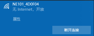
Entering Configuration Mode
- Short press the function key (about 0.5 seconds)
- Device hotspot name displays as NE101_XXXXXX
-
Connecting to Management Interface
- Connect your phone/computer to the device WiFi
- Access http://192.168.1.1

Core Function Configuration
Image Capture Settings
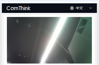
Key Parameters:
-
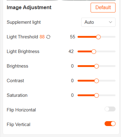
Flash Mode:
- Intelligent Auto (default)
- Timed On
- Forced Off
-
Image Adjustment:
- Brightness grading adjustment (0-90 levels)
- Three-axis adjustment (brightness/contrast/saturation)
- Image mirroring function
Capture Plan Configuration

Working Modes:
- Timed Capture: Set specific time points
- Interval Shooting: Set cycle period (5 minutes - 24 hours)
- External Trigger Mode: Trigger via Alarm-In signal
- Manual Mode: Capture triggered by button press
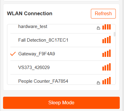
Network and Data
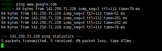
Network Test (Serial Connection):
# Example of executing ping test via serial port
ping www.example.com -c 4
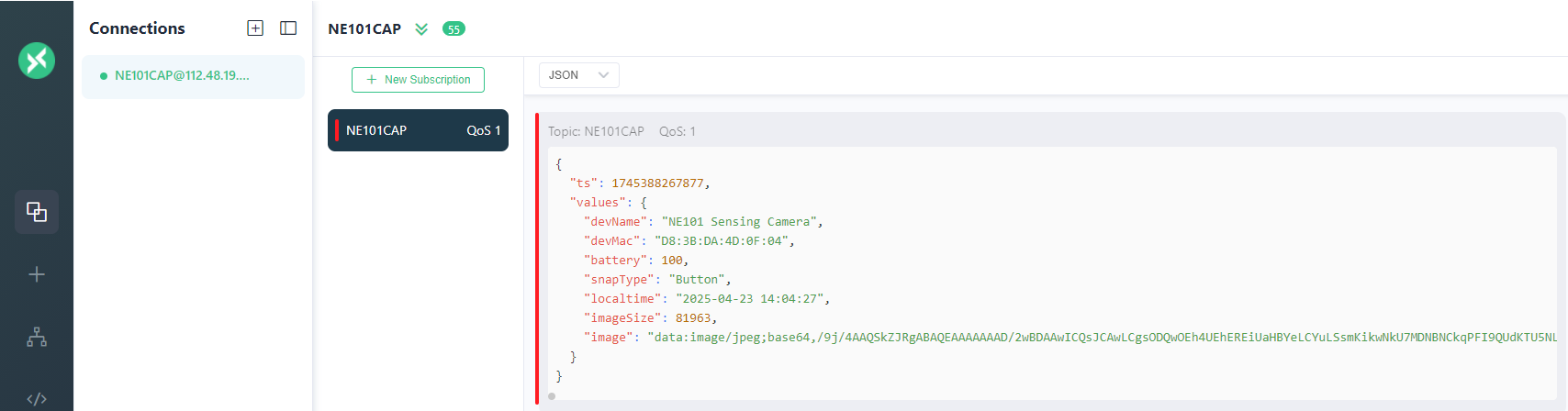
Data Reporting:
- Configure MQTT server parameters
- Verify data stream using MQTTX tool
- Check reporting status

Function Verification Process
- Enter sleep mode (auto wake-up after 5 minutes)
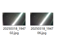
- Trigger capture task (timed/manual/external trigger)
- Confirm image quality (resolution/exposure/focus)
- Verify data upload (server reception confirmation)
Detailed Device Working Modes
| Mode | Trigger Condition | Duration | Main Function |
|---|---|---|---|
| Initialization | Auto on power-up | ~1 minute | System self-check, time synchronization |
| Configuration | Button trigger | 1-5 minutes | Parameter setting, status check |
| Working | Plan trigger | As needed | Image capture, data reporting |
| Sleep | Auto entry | As planned | Low-power standby |
Advanced Functions
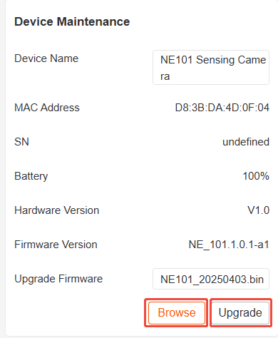
Device Maintenance
- Hardware Reset: Short press reset button to restart
- Device Information: View MAC address/firmware version
- Wireless Upgrade: Supports OTA firmware updates
Technical Support: It is recommended to complete a full function test during the first use.